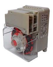
| Type: DFB3 |
| |
|
| |
|
APPLICATIONS:
for automatic defrosting of industrial refrigeration plant, commercial visicoolers anddisplay counters.
- From 1 to 12 defrost cycles per day thanks to non detachable tabs.
- Defrost time easily adjustable from 1 to 56 minutes.
- Fan delay easily adjustable from 0 to 15 minutes (for D53.82).
- Independent power supplies for synchronous motor and for switches.
- Safety guardfor wiring terminals in accordance with CEI 23 - 11.
|
OPERATING INSTRUCTIONS:
SUPPLY VOLTAGES:
See ratings on the timer label.
Availability: 220/240 (+10% -15%)
On request: 24V-110/120V
FREQUENCY OF SUPPLY:
Standard: 50 Hz -
On request: 60 Hz
OPERATING TEMPERATURE:
CONTACT RATING:
ELECTRICAL CONNECTIONS:
Max 8 FASTON terminals 6,3mm x 0,8mm
ACTION TYPE AND COMPLEMENTARY FEATURES:
REAR MOUNTING:
With 2 screws Ø 4mm. See fig. 1
DIN RAIL MOUNTING (DIN/EN 50022):
Two possibilities by means of an adaptor (on request). See fig. 2
POLLUTION SITUATION:
APPROVALS:
ELECTRICAL CONNECTION PROTECTION:
The cover, supplied not fastened with the screw after wiring.
NB: the slots for the passage of the wires can be widened removing the pre-cut central sector
TIMING:
See fig. 3 - switching intervals:
T1 and T" adjustable (T1+T2=70 min max)
Type
DFB3.72: the two contacts switch simultaneously
From 1 to 12 defrost per day
|
|
- TYPICAL APPLICATIONS:
See fig. 4.1: Defrosting with hot gas
See fig. 4.2: Defrosting with fan delay
See fig. 4.3: Defrosting with resistor
Fig.4 shows the patterns applied to the DFB3 model
WIRING: See fig. 4
C=cooling T=cooling thermostat D=defrosting
R=relay V=reverse cycle valve F=fan
- PROGRAMME SETTING:
See fig. 5.
Set defrost period T1 by aligning pointer (A) to number of wanted minutes of graduation (B).
Set delay period T2 (only DFB3.82) by aligning pionter (C) to number of wanted minutes of graduation (D).
Set number of defrost per day by pushing down one or more trips (E).
To apply the diagrams DFB3.72 and DFB3:81, position the index (C) on the value 0 of the scale (D).
|
|
- TIME SETTING:
See fig. 5
Turn knob (G) clckwise until tip of actuator (H) aligns with the actual time on the hour dial (F).
Note 1: The unit switches on around the odd hour of each lowered trip.
Note 2: Each revolution of knob (G) rotates dial (F) 2 hours.
- EXAMPLE:
T1=30 mins - T2=5 mins - Three defrosts per day at 7.00 hrs, at 15.00 hrs and 21.00 hrs - Actual time=2.00 hrs:
1) Pointer (A) on nick 30 of graduation (B).
2) Pointer (C) on nick 5 of graduation (D).
3) Trips (E) 6-8, 14-16, 22-24 pushed down.
4) Nick 2 of the dial (F) aligned with tip of actuator (H).
|